Reverse Engineering
2D Drawings to 3D models and vice versa
Transforming OLD 2D OEM drawings into accurate 3D CAD files digital models, So our engineers can replicate or improve existing parts and designs.
Converting 2D OEM drawings into 3D CAD models allows for easier modifications and integration into modern systems or opens the posibility for CAM
Existing 3D STEP files can be used to create detailed 2D draftings for manufacturing, or archive purposes, ensuring that all specifications, dimensions, and tolerances are clearly defined.
STL - 3D CAD Surface Comparisson
1
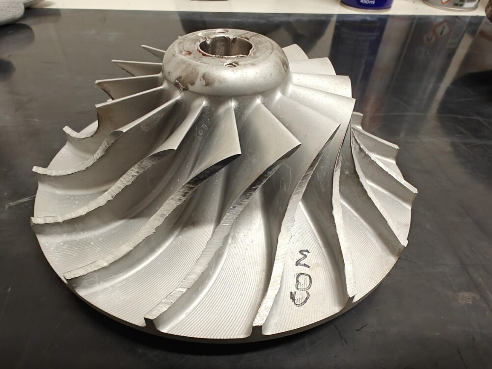
Collect Data
2
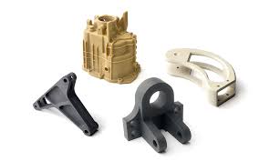
SCAN
3
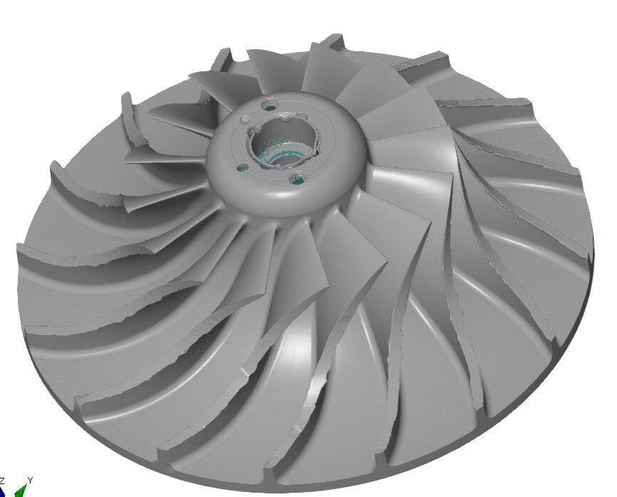
STL-FILE ANALYSE
4
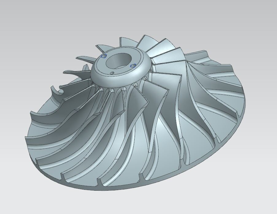
3D CAD MODELING
5
SURFACE COMPARISON
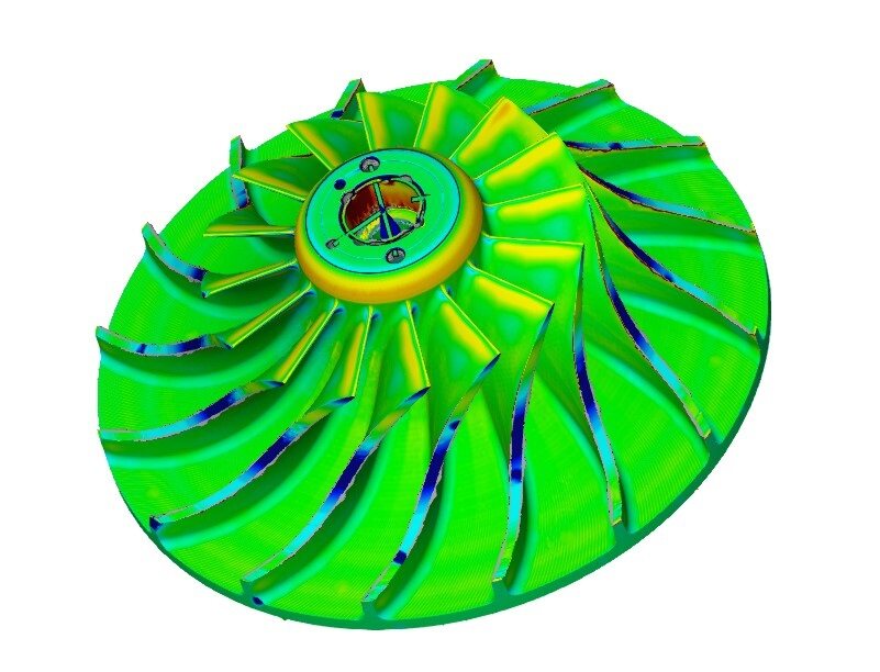
The process begins with capturing scan data of the physical part, typically using a 3D scanner. This scan generates an STL file, which provides a detailed digital representation of the part’s geometry. Using software like GOM Inspect, the scan data is analyzed for accuracy and precision. Then, the data is used as a reference to design a new 3D CAD model from scratch. This CAD model is created with design intent, taking into account factors like functionality and manufacturability.
Once the new 3D CAD model is complete, a surface comparison is performed between the STL scan data and the new CAD model. This comparison helps to identify deviations or inaccuracies, ensuring the new design matches the original part's shape and specifications. This process ensures that any design improvements made are within tolerances and that the final model meets both the original part's geometry and the new design's requirements.